Video: https://youtu.be/wqoUfVyAGDM
Transcript:
If you have any custom 3D objects in DWG, DXF, SKP (Google™ SketchUp), 3DS,OBJ or IFC format, you can import them into your Envisioneer drawing. Many sites on the Internet offer free downloading of objects for your convenience. Typically, these are objects such as furniture and appliances. You can import a custom object directly into your drawing using the Object Import Wizard. Once inserted, you can edit its properties just as you would edit any element in your drawing.
To import a custom object into your drawing:
- Select File > Import > Object Wizard.
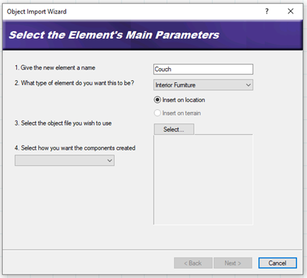
- In the first edit box, type a name for the element.
- From the element drop box, select the type of element you are importing.
- If you selected Exterior Furniture, Exterior Accessories or Exterior Lighting, you have the option of inserting the element on the floor of the current building location, or the terrain. Select either the Insert on location or Insert on terrain radio button. (All other element types have one of the options pre-selected for you, with the other option disabled.)
- Click the Select button.
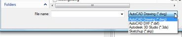
- In the Open dialog, locate and select the file that you want to import, then click Open. You can import DWG, DXF, SKP, 3DS and IFC files.
NOTE: If this is a SketchUp block, you are then asked if you want to force the block to be single sided. This will help reduce the size of the imported block but may have undesirable effects. We do recommend selecting this option and reviewing the block to make sure it looks complete. Select Yes for this dialog. If the block is over 4MB or is an OBJ file. A dialog box will appear that notes how the block will be optimized for insertion. Some of the following steps will not apply to the large blocks or OBJ files.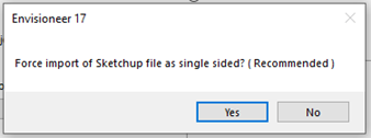
- Specify how you want the components created by making a selection from the drop box. For DWG and DXF files you can choose from Colors or Layers. Since 3DS and IFC objects are essentially an assembly of materials, the only selection for 3DS and IFC objects is Materials. (This step does not apply to SketchUp files.)
- Click Next.
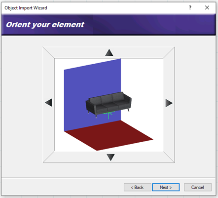
- On the Orient your element screen, use the arrows to rotate the model so it will be correctly oriented when inserted in a drawing.
- Click Next.
- If the object is a door or window, the Position the insertion point of your element screen will appear. Specify where along the object’s height (Z Axis) you would like to position the object’s insertion point. Use the slider to move the insertion point up or down. To offset the door/window frame from the wall surface, enter an offset value in the Frame Offset edit box.
- Click Next.
- Depending on the file types, and additional field will appear. For some file types, the program needs to know what units were used to create the object to be converted into an appropriate size. If you know what units were used to create the object, select the units from the units drop box. Otherwise, select the unit of measure that will result in a logical Resultant Width, Resultant Depth and Resultant Height. Selecting Custom lets you specify a custom scale in the Custom Scale edit box. The scale is the multiplication factor of the units used for objects in the block. For example, if you’re converting a file that you assume was created in feet and inches, the scale is 25.4.
- Click Next.
The next screen lists the object’s individual components. By clicking the appropriate eye icons, you can specify which components you want to display or hide in 3D.
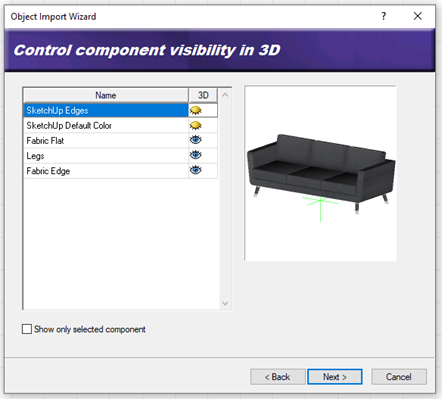
Enabling the Show only selected component check box displays only the currently selected component in the object preview. This helps you distinguish between the object’s individual components.
To rename a component, double-click it, then type the new name and press Enter.
- Click Next.
- The Display Components to Generate Plan View dialog lists the object’s components again, but this time you can specify which components you want to display or hide in 2D plan view. If the block has 2D edges that make up a good 2D representation of the block turn their visibility on. If it doesn’t you can use the utilities in the lower right of the dialog box to make a new 2D image.
 To create a custom plan view, select either Outline or Slice below the preview window to specify how the plan view is to be created. To create a simple outline based on the object’s footprint, select Outline. To create a slice through the object, select Slice, and then use the slider control next to the preview window to specify the position of the slice by moving the toggle up or down until the desired 2D image appears in the preview. Once the plan view has the desired appearance in the preview window, click to the plus sign to add the view to the list of components.
- To control the visibility of components within the custom plan view, click on the eye next to the component to hide or show it.
- Click Next.
- Click Finish.
- Click to insert the new element in your drawing.
- Right-click and select Finish.
- After inserting the new block into the drawing area, you can edit the properties further by double clicking on the new element.
- On the Basic tab you can adjust the size and orientation of the block.
 To create a custom plan view, select either Outline or Slice below the preview window to specify how the plan view is to be created. To create a simple outline based on the object’s footprint, select Outline. To create a slice through the object, select Slice, and then use the slider control next to the preview window to specify the position of the slice by moving the toggle up or down until the desired 2D image appears in the preview. Once the plan view has the desired appearance in the preview window, click to the plus sign to add the view to the list of components.
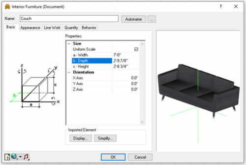
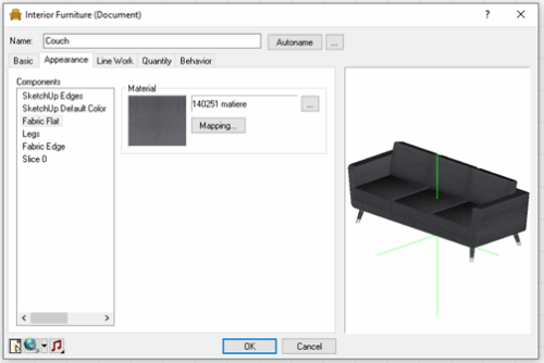
- On the Appearance tab you can adjust the materials being used and the mapping of the materials as they appear on the components.
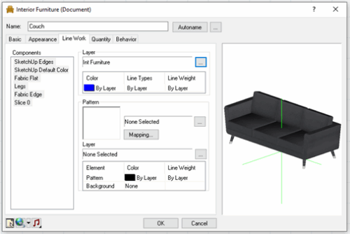
- On the Line Work tab you can adjust the lines for the components so that they use the correct layer when visible in 2D and in your worksheets.
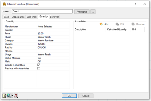
- On the Quantity tab you can specify all your quantity information so that your new item reports correctly.
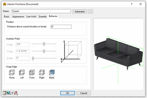
- On the Behavior tab you can adjust the Position the element will sit in your design above the terrain and define a snap edge for controlled placement when the Collision option is enabled.
- Select the OK button to accept all the adjustments to the new block
If you want this item to be part of our catalog so you can import it into future projects:
- Select File > Catalogs > Save Element to Catalog, or click the down arrow next to the Catalogs button
 on the Standard toolbar and select Save Element to Catalog. Your pointer changes to a catalog cursor.
 - Select the element in your drawing.
- Click Yes to save the element. You are asked if you want to save another element to the catalog.
- Click Yes if you want to save another element to the catalog, or No to finish.
 on the Standard toolbar and select Save Element to