Video: https://youtu.be/D3_CTY7gcRY
Transcript:
Creating a Pier or Stump Foundation is ideal for locations with uneven terrain or flood-prone regions because the floor structure will be elevated above the terrain. Adjusting the building locations to accommodate this type of foundation can be achieved in Envisioneer.
We must open the Building Locations Dialogue to adjust the building locations for our pier or stump foundation.
-
-
-
- Go to Settings > Buildings Locations or select the Building Locations button in the lower left corner.
- In the Building Location dialog, highlight the Foundation row and double click the Floor Level value to edit it. Type 0’.
- A dialog box will appear asking, “Do you want to update the floor levels affected by current modification as well?”. Click Yes.
- Double click on the Wall Height value and type 2’.
-
 We want our Piers or Stumps to be 2’ high. When the Wall Height is defined, any posts or columns we add will refer to the Building Location Wall Height.
 -
-
- Highlight the Ground Floor row.
- Change the Floor Level value to 3’ 9 ¼”.
 We want our Piers or Stumps to be 2’ high. When the Wall Height is defined, any posts or columns we add will refer to the Building Location Wall Height.
The structure we will be building has a 2×10 Skirt and a 2×12 Structural Floor with 3/4”
-
- The green check mark in the Building Locations dialog box refers to the current location—the location that you will be modeling on when you exit the dialog box. We will be starting our structure at the Foundation location. Double-click in the row above to move the check mark to the Foundation row.
- Click OK to exit the Building Locations dialog and save the changes.
Now that we have adjusted our Building Locations we need to add the Piers to the Foundation Location.
-
-
- Ensure that the Foundation is listed as current the Building Locations drop-down menu in the screen’s lower left corner.
- Select Insert > Columns or the Columns button under the Building tab.
- In the catalog panel to the right, select the 8×8 Wood Post from the Wood Columns folder.
- Move your cursor onto the drawing screen and area and left-click to insert the wood post into the model. This will be the first post in our design. Right-click and select Finish.
- Select Insert > Footings > Mono Footings Attached to Columns or select the drop-down button next to the Footings button under the Building tab and select the Mono Footings Attached to Columns option.
- In the catalog panel, select the Cylindrical Mono Footing folder and the 16” Cylindrical Mono Footing.
- Move your cursor over the Column we just inserted and left click to attach the footing to the column. Right click and select Finish.
- Left-click to select the Footing, and then hold down the shift key on your keyboard. Left-click to select the Column so they are both selected.
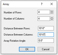
- Right click and select Array.
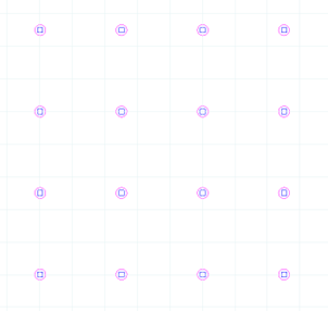
- In the Array dialog box, we will create 4 rows and 4 columns, both spaced at 10’. Once you have the values added, click OK.
-
-
-
- We now have the Pier Foundation that will support our Ground Floor construction.
-
Next, we will create a skirt around the piers to support the floor joists and cover the beams.
-
-
- Select Insert > Structural Floor > Structural Floor by Picking Points or by selecting the Structural Floor dropdown button and then selecting Structural Floor by Picking Points.
-
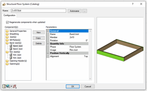
The catalog panel on the right will populate with structural floors. We will create a new Structural Floor of just 2x10s for the Rim and Band Joints to act as a Skirt.
-
-
- In the catalog, under the No Sill Plate folder, select the 2×10 Floor System w/ 3/4″ OSB No Sill Plate and then right-click and select Add Element.
- Change the name to 2×10 Skirt. Under the Components, select the Sheathing option.
- Under the Parameters, set the Include option to No to remove the sheeting.
- Click each member listed under Components and click Delete to remove all the members except for the Band and Rim Joist.
- Select the Band Joist and click the Copy button to double up the boards.
-
-
-
- Double up the Boards by clicking the Rim Joist member and the Copy button.
- Click OK to accept the changes and exit the dialog box.
- Select the new 2×10 Skirt Structural Floor and move the cursor onto the drawing screen area.
- In the lower left corner of the screen, you will see a Base Height option. We want our Skirting to sit on top of the piers, so we will enter a value of 2’ 9 1/4” and press TAB on the keyboard to lock that value in. This is the height of the Pier plus the height of the 2×10 member.
- Now pick points to define the corners of the skirt. Left click on the outside corner of each corner column. After you have picked the four points, right click and select Finish.
-
Next, we will add Beams between our Rim Joists and over the Piers.
-
-
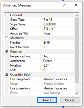
- Select Insert > Members > Advanced Members, or under the Building Tab, select the dropdown arrow beside the Members button and select the Advanced Members option.
- In the Advanced Members dialog, set the Offset to 2’9 ¼”
- Click Member and a button with three dots will appear, click it.
- In the Catalog Access dialog box, select the 2×10 and click OK.
- Set the No of Members to 3.
-
-
-
- Click Insert.

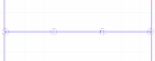
Left click on a middle pier on the left to start a beam and move your cursor across the foundation to the other side, and left click again to finish the beam. - Right click and select Repeat to create the second beam.
- Once the second beam is added, right click and select Finish.
- Click Insert.
-
On the Ground Floor location, we can now add the Structural Floor that will sit on top of our Skirt and Piers.
-
-
- In the Building Locations drop-down in the lower left of the screeen, select Ground Floor.
- Select the Structural Floor button and then in the catalog under the No Sill Plate folder select the 2×12 Floor System w/ 3/4″ OSB No Sill Plate option.
- Left-click on each corner around the perimeter of the Piers visible below. Right-click and Finish.
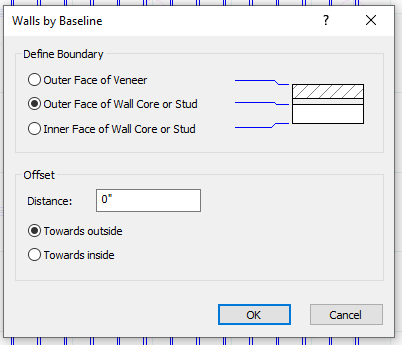
- We can now add the Walls that will sit on top of the structure. Select Insert > Walls > Walls by Baseline or under the Building tab select the drop-down button beside Walls and select the Walls by Baseline option.
- In the catalog, select the 2×6 Cement Board Panel Wall and left-click on each corner around the structural floor we just added. Right-click and Finish.
- In the Walls by Baseline dialog, select the Outer Face of Wall Core or Stud option. This will place the framing to the edge of the structural floor, allowing the veneer to cover the floor. Then select OK.
-
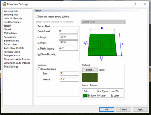
 You can view your design in 3D by selecting any of the default 3D Cameras. When selected you will notice that the terrain is being cut from below our design. We must adjust this so that the terrain carries under our structure.
-
-
- Go to Settings > Document Settings > Terrain and then uncheck the Auto -cut terrain around building Then select OK.
-
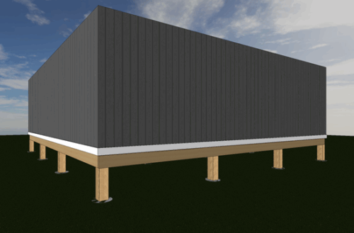
We have now created a Pier Foundation that elevates our design off the ground.